We have problems with condensation in our house (UK weather). In order to evaluate the situation, I planned to log the day-to-day humidity and temperature. It seems to be a popular subject, with plenty of material online.
The DHT-22 is a popular sensor, fairly cheap, 3.3V and 5V compatible, with a very simple wiring: Only need GND, VCC, DATA. It seems to have a broad support on almost all platforms.
My first attempt was done using a Raspberry Pi with a web server to provide the visualisation tools. However I thought it was a bit overkill, and I wanted to experiment with something a bit less high-level, so I looked at the Arduino family. I made the first prototype using a cheap Arduino nano clone.
The DHT-22/Arduino integration worked really well. However then came the problem of the reporting, that I had for free with the Raspberry pi’s integrated wifi. With the Arduino, I could only store a limited amount of data and had to find ways to export it through the serial link. It was not very efficient.
To solve this problem I bought a tiny Wifi ESP-01 module (based on the ESP-8266 chip, this module provide a serial link that you can use to send and receive data over Wifi using the AT command set. I had quite a few issues, essentially related to current limitations because the ESP-8266 require a large peak current. I was not the only one confused by the various conflicting blog posts on the subject.
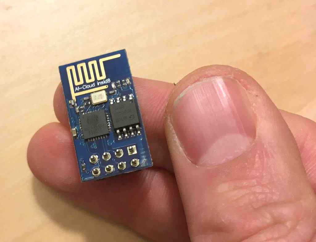
This thing is *Tiny!*. And it contains a complete system with a microcontroller, wifi module and memory
After a while, I found out that the wifi chip itself can be programmed using the Arduino libraries and IDE, so I gave it a try. I could then directly drive the DHT-22 from the ESP-01, and send the data to AWS Lambda without any extra component. It is much less straightforward than the simple Arduino flashing, and there are quite a few instructions that are not obvious, so I have documented some of my mistakes during the process. I recommend the very good documentation for the ESP-8266 Arduino library.
Parts list
- Breadboard
- buck
5V -> 3.3V converter(from a Chinese website) - a 10kOhm resistor for the DHT pin
- DHT-22
- USB to serial adapter: pick one compatible with 3.3V on RX/TX.
Things I wish I knew when I started ESP-01 programming
- VCC: the ESP-01 is 3.3v only, and can use up to 500mA when booting up. This means:
- VCC must be 3.3V, and the RX pin must not be directly receiving 5V from your USB to serial adapter, you need to set your adapter to 3.3V or use a voltage divider.
- You need a pretty powerful power source. I wasted a lot of time trying to figure out why the ESP-8266 wasn’t behaving correctly. The USB to Serial converter provided 3.3V but with not enough current, an LM1117 was too inefficient to drive the ESP through USB, so I ended up using a
Buck 5V -> 3.3vconverter.
- There are two UART on the ESP-01.
UART0usesGPIO1(TX) andGPIO3(RX), whileUART1usesGPIO2for TX and do not expose the RX port. This is usually poorly documented in the tutorials, but when you start in programming mode, the chip will send messages usingUART1(TX onGPIO2) and will expect the new program onGPIO3. - Every time the ESP-8266 boots up, it will output a message on UART1 (TX on
GPIO2) with the current mode (baud rate is74880). That way you can check that it is booting in programming mode (UART). See the documentation. Here is a sample message received after a hardware reset (rst cause: 2), in programming mode (boot mode:(1):
rst cause:2, boot mode:(1,6)
- If you do not want to have to change your TX pin from
GPIO2toGPIO1every time after programming, you can tell Arduino to use the UART1 TX pin by default for the Serial object withset_tx(see documentation):
Serial.begin(115200);
Serial.set_tx(2);
- How to start in programming mode:
- GPIO15 must be DOWN: it is not exposed on the ESP-01 and is down by default, no need to do anything
- GPIO0 must be DOWN
- GPIO2 must be UP: You should have it connected to your serial port. No problems here, there is a pull-up, it is UP by default, no need to do anything.
I will talk about the software side of things in a later post.
Completed Sensor module
What really impressed me with this module is the fact that after the programming stage, you only need a very limited amount of components to have a perfectly working sensor:
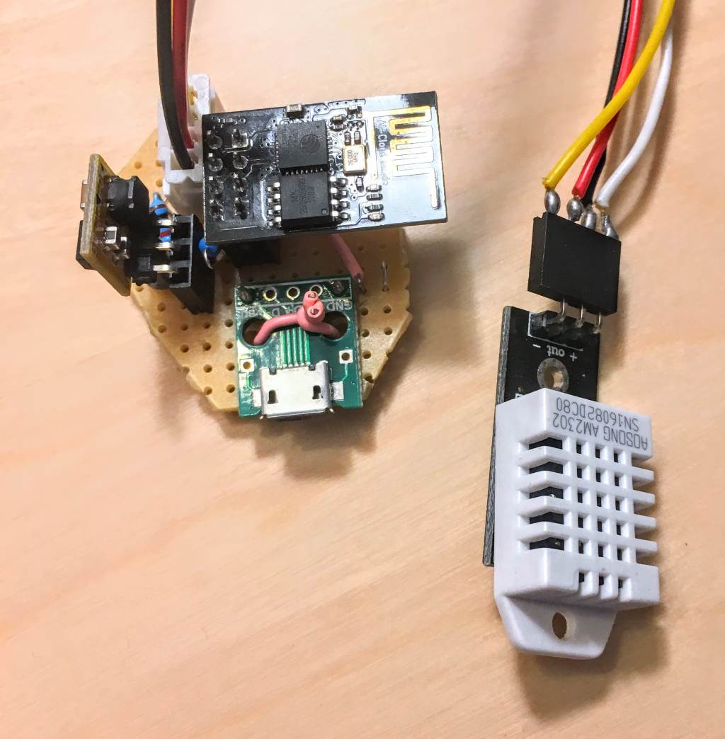
The last prototype.
You can see the buck converter on the left, the ESP-01 on the top and the USB connector (power only) at the bottom. There is an extra capacitor under the buck converter to smooth the output of the converter.
I originally planned to power everything through a battery pack, but the ESP-8266 need to be awaken externally, and the ESP-01 does not expose the Pins required. This article gives a nice overview of the sleep capabilities of this chip.